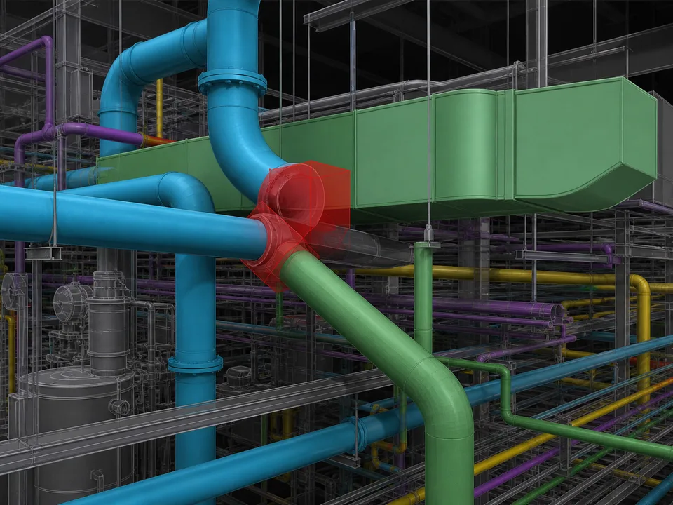
BIM for Prefabrication: Building Factory-Ready Models That Install Cleanly
Master BIM for prefabrication—LOD, tolerances, logistics, Scan to BIM verification, and QA methods that keep modular and rack assemblies installable.
BimzstudioJul 29, 202616 min
BIM prefabricationmodular constructionMEP racksDfMAScan to BIM
BIM for Prefabrication: Building Factory-Ready Models That Install Cleanly
Prefabrication fails in public when a module arrives that does not fit. It fails quietly when crews spend nights cutting factory work apart. In both cases the root cause is often the same: the BIM was not fabrication-ready, not tolerance-aware, or not verified against real site conditions. Prefabrication is manufacturing. Manufacturing needs product definitions, not approximate coordination models.
This guide explains how to use BIM for prefabrication across racks, modules, façades, and repetitive assemblies—with special attention to retrofit contexts where Scan to BIM decides whether factory geometry survives first contact with the building.
Prefab tolerances leave little room for fuzzy as-built assumptions.
Owners want prefabrication for speed, quality, and labor predictability. Factories want stable geometry and early freezes. Site teams want modules that land without drama. BIM sits in the middle as the contract between design intent, manufacturing constraints, and installation reality.
The problem is that many project models are optimized for visualization or soft clash detection, not for cut lists, weldments, spool pieces, connection tolerances, lifting points, and transport envelopes. When those data are missing, factories improvise—and improvisation does not scale.
Retrofit prefabrication adds another failure mode: the “as-designed existing” that never existed. Without measured Scan to BIM and deviation control, perfect modules fight imperfect buildings.
Why It Happens
Prefabrication BIM breaks down when:
LOD is vague. “LOD 400” is stated without defining which connections, fasteners, and accessories are included.
Tolerances are ignored. Interfaces between module and site structure need stack-up analysis.
Design keeps changing after shop release. Factories cannot absorb weekly redesigns without cost.
Logistics are an afterthought. A rack that fits the corridor in model space may not fit the elevator or street crane radii.
Trades model in isolation. Rack collisions with gravity systems appear after fabrication.
QA stops at clash detection. No prototype, no scan verification, no dimensional inspection plan.
Contracts do not freeze interfaces. Responsibility for site-measured dimensions is unclear.
These are process failures more than software failures. Tools enable DfMA; they do not enforce discipline by themselves.
Industry Examples (EU/USA)
Europe
Bathroom pods, timber modules, façade cassettes, and technical risers are common in Northern and Western Europe. BIM/DfMA workflows integrate architects, manufacturers, and installers earlier. OpenBIM exchanges appear more often in public work, forcing clearer information requirements for fabrication partners. Energy retrofit programs increasingly prefabricate façade upgrade panels—success depends on accurate existing-conditions models from scans.
United States
Healthcare, data centers, semiconductor, and commercial high-rise projects drive multi-trade MEP rack prefabrication and modular equipment skids. GC-led coordination models feed detailing shops. Labor shortages make factory hours strategically valuable. Industrial owners prefabricate pipe modules for turnarounds where site time is the scarce resource; Scan to BIM of tie-in points is non-negotiable.
Across both markets, the winners treat the model as a product definition package with release gates.
Technical Explanation
Fabrication-ready LOD must include interfaces and clearances.
DfMA information content
A fabrication-ready BIM package typically includes:
Exact geometry of assemblies and subassemblies
Connection details and interface plates
Material specs and finishes linked to elements
Unique part/assembly IDs matching shop travelers
Weight, CG, lifting points
Tolerance and shim strategies
Transport envelope and orientation
Installation sequence and temporary bracing
QA checkpoints and inspection dimensions
Tolerance and interface control
Define:
Factory tolerances
Site structure tolerances (especially existing conditions)
Scan-derived deviations should update interface geometry before shop drawings freeze.
Model federation strategy
Keep design intent models, fabrication models, and site verification models related but not confused. Version gates: coordination issue → fabrication release → as-fabricated → as-installed.
Scan to BIM role
For retrofit: capture tie-ins, penetrations, structural faces, and access paths. Model only what controls fit. Produce deviation maps against design assumptions. For new build verification: scan slabs/embeds before module delivery to catch drift.
Data handoff to factory systems
BOM exports, DSTV/CNC data where applicable, spool drawings, and QR-linked element IDs close the digital thread. If the BIM ID dies at the factory door, traceability collapses when site problems appear.
Best Practices
Scan verification of install conditions protects factory schedules.
Write a prefab BEP annex with LOD matrices per assembly type.
Freeze interfaces earlier than interiors.
Prototype the first module and scan it if needed.
Coordinate logistics in the model (path studies, crane picks).
Assign a single interface owner for each module-to-site joint.
Use Scan to BIM for all critical retrofit tie-ins.
Control changes with release waves, not continuous tinkering.
Include access and maintainability in prefab design reviews.
Track factory NCRs against model causes to improve rules.
Close the loop with as-installed scans on early levels.
Step-by-Step Prefab BIM Workflow
Step 1: Select prefab scope by ROI and access
Choose assemblies with repetition, labor intensity, and constructability pain.
Step 2: Define product breakdown structure
Modules, racks, panels—IDs, boundaries, and interfaces.
Step 3: Capture existing conditions if retrofit
Scan, register, model tie-in critical geometry, publish deviation report.
Step 4: Design for manufacturing and assembly workshops
Include connections, hangers strategy, and clearances.
Step 6: Federate and clash by priority
Resolve interface clashes before shop release; park non-critical interior clashes carefully.
Step 7: Run logistics simulation
Path, staging, and lift studies with real constraints.
Step 8: Issue fabrication release package
Drawings, models, BOM, IDs, tolerances, QA plan.
Step 9: First article inspection
Measure against model; adjust before mass production.
Step 10: Install, verify, feed back
Scan or measure installs; update rules and remaining releases.
Case Study
A US hospital vertical expansion used multi-trade corridor racks for clinical floors and Scan to BIM for connection into an existing podium. Early design assumed flat soffits and regular steel. Scans showed camber, fireproofing thickness variation, and a conduit bank undocumented in archives.
The prefab BIM workflow responded by:
Remodeling rack top-of-steel interfaces from scan-based structure
Adding adjustable hanger strategies within defined tolerance bands
Prototyping one rack, laser-checking critical dimensions, and updating connection plates
Path-studying elevator and loading dock constraints that forced rack segmentation changes
Outcome: racks installed with minor shim adjustments within planned tolerance; no fleet-wide field cutting. The podium interface—historically a change-order machine—stayed within contingency. The project’s lesson was blunt: prefab BIM without Scan to BIM at the existing interface would have fabricated the wrong product efficiently.
Common Mistakes
Calling coordination models “fab models.”
Freezing shops while design still churns.
Ignoring transport and hoist constraints.
No tolerance stack-up at interfaces.
Prefab without multi-trade federation.
Skipping prototypes to save schedule—then losing more schedule.
Poor ID discipline between model and travelers.
Assuming as-built structure matches design.
Over-customizing every module, destroying factory learning.
Leaving maintainability out—modules that cannot be serviced are future cost bombs.
Expert Tips
Build a tolerance matrix poster for the war room; ambiguity kills prefab.
Keep a “do not cut in field” red list for factory warranties and quality.
Model temporary lifting gear envelopes if they govern design.
For façades, prioritize surveyed slab edges and embed locations over aesthetic BIM detail early.
Use color status on assemblies: coordinating / released / fabricating / shipped / installed.
Require factories to report dimensional deviations against BIM IDs digitally.
Train installers on interface intent—shims are strategy, not shame.
When using openBIM, validate fabrication property sets explicitly.
Protect one senior detailer as interface guardian across trades.
After each floor, hold a 30-minute “what the model missed” huddle.
Future Trends
Factories will consume BIM data more directly into CNC and robotic assembly. AI will propose rack routings under prefab constraints, with humans approving. Continuous site scanning will update interface geometry before shipment. Modular platforms will standardize option libraries, shifting BIM from one-off detailing toward configuration of product systems. Digital twins of modules will carry maintenance access and spare parts data from factory day one.
The differentiator will remain interface control and release discipline—technology amplifies both good and bad habits.
Interface Control: The Heart of Prefab BIM
Most prefabrication failures are interface failures. Mid-module geometry can be imperfect and still install; a wrong connection plate or an unmeasured existing soffit will not. Build an interface register with columns for:
Interface ID and assembly pair
Responsible author (trade/designer)
Controlling dimensions and datum
Tolerance budget and compensation method
Survey/Scan to BIM requirement (yes/no)
Freeze date
Verification method (jig, laser check, scan)
Status
Review the interface register in the same meeting cadence as the clash schedule. If an interface lacks an owner, it will fail in the field.
Logistics modeling that prevents factory success from becoming site failure
Include in the federated model or linked studies:
Module/rack bounding boxes with packing orientation
Truck envelope and site access routes
Elevator/hoist/crane capacity and reach
Staging laydown footprints
Temporary protection and weather constraints
Installation sequence dependencies (what must be absent for a rack to fly)
A rack that “fits the corridor” but cannot leave the truck bed is not a BIM success. Path studies are first-class design, not a logistics afterthought.
Quality gates from shop to install
Gate A — Coordination complete: multi-trade clashes at interfaces closed; logistics cleared. Gate B — Fabrication release: LOD/content checklist signed; IDs locked; BOM frozen for the wave. Gate C — First article: measured vs model within tolerance; NCRs dispositioned. Gate D — Ship: traveler docs match BIM IDs; lift plan attached. Gate E — Install verify: as-installed checks; feedback to remaining waves.
Skipping gates to “save time” is how entire floors of racks become field modification projects.
Retrofit prefab special rules
Never fabricate critical tie-ins from archive drawings alone when scans are feasible.
Publish deviation reports to all trades before detailing.
Prefer adjustable interfaces within defined ranges over theoretically perfect fixed geometry.
Model fireproofing, finishes, and existing hanger forests when they consume envelope.
Re-scan after demolition if demolition changes the interface you fabricated toward.
Commercial and contractual notes
Define who pays when site dimensions differ from the coordinated model. Define what “fit” means numerically. Define change cutoff dates for each release wave. Prefab without commercial clarity becomes a dispute generator that makes teams afraid to prefabricate next time—even when the engineering was sound.
People and skills
Detailers need manufacturing literacy. Modelers need to understand weld access, fastener spacing, and shipping splits. Installers need to understand which dimensions are adjustable versus sacred. Cross-train with factory visits; a day on the shop floor prevents months of naive modeling.
Assembly types and modeling emphasis
MEP multi-trade racks: prioritize hanger strategies, gravity clearances, valve access, firestopping provisions, and corridor logistics. Scan existing structure and large obstructions on retrofit corridors.
Equipment skids: prioritize nozzle locations, maintenance clearances, structural baseplates, and shipping splits. Coordinate early with equipment vendors’ native models.
Volumetric modules (bathrooms, plant rooms): prioritize structural interfaces, wet/dry connections, fire/acoustic separations, and transport envelopes. Survey slab edges and service risers obsessively.
Façade cassettes/panels: prioritize slab edge surveys, embed locations, waterproofing interfaces, and stack tolerance. Aesthetic BIM detail is secondary to dimensional control early on.
Structural prefabricated elements: prioritize connection geometry, camber, lifting, and erection sequence. Verify seats with scans on rehab/ABC abutments.
Each type needs its own LOD annex. Copy-paste LOD from a building shell BEP into a rack package and you will under-model what matters.
Digital thread and traceability
When a site NCR appears, you must answer: which BIM version, which release wave, which factory traveler, which inspection record? QR codes or stamped IDs that match element Unique IDs close that loop. Without traceability, every failure becomes folklore and nothing improves systematically.
Measuring prefab BIM success
First-time fit rate at interfaces
Field cut/weld hours per module (should trend down)
Factory NCR rate attributable to model errors
Logistics rejects (will not fit path/truck)
Schedule adherence of release waves
Install crew feedback scores on clarity of interface intent
If these metrics are flat after three waves, your BIM is not yet fabrication-grade—regardless of how good it looks in a viewer.
Collaboration rhythm that works
Twice-weekly interface huddles during detailing peaks (30 minutes, decisions only)
Weekly federated clash on prefab envelopes and site path
Release-wave gate meeting with factory, GC, and trade detailers present
Post-install 30-minute feedback after first three modules on each floor type
Monthly metrics review against the success KPIs above
Meetings without gates are theater. Gates without meetings become email chaos. Use both.
When not to prefabricate
If design is still volatile, access is undefined, existing conditions are unknown and unscannable before award, or the team lacks interface ownership, stick-build—or partial prefab of non-interface internals—may be wiser. BIM for prefabrication includes the judgment to say not yet. Forcing prefab into chaos transfers the chaos into a factory and multiplies it.
Content libraries for prefab speed
Standardize rack typologies, connection families, hanger families, and parameter sets. Automation and junior detailing accelerate only when the library is trusted. Treat library changes like engineering changes—reviewed, versioned, and communicated to factories. A wild-west family folder will sabotage prefab BIM faster than any clash.
Invest once in a vetted library across a portfolio of similar buildings (healthcare floors, data hall corridors) and the marginal cost of each new prefab package falls sharply—the real ROI story behind “BIM for prefabrication.”
Safety, access, and maintainability
Factory-perfect modules that block future filter changes or valve access are failures deferred. Include maintainability reviews in fabrication gates. Model access zones, coil-pull spaces, and code-required clearances as clashable solids. Prefab BIM is not only about getting modules in—it is about living with them for twenty years without cutting them apart.
Also verify firestopping and smoke barrier continuity at module interfaces. These details are easy to omit in coordination models and expensive to remediate after occupancy.
Document lift plans and temporary bracing in the release package so site crews are not inventing methods that fight the designed module. Prefab BIM ends at successful install and safe temporary states—not at the factory gate.
FAQ
What LOD is required for prefabrication?
Whatever your annex defines for that assembly—typically including connections, supports, and interfaces. The label without content is useless.
Can BIM support volumetric modular buildings?
Yes—especially for coordination, logistics, and interface control between modules and foundations/site systems.
Is Scan to BIM mandatory?
For retrofit tie-ins and verification of critical embeds/structure, it is strongly recommended. For pure new build on well-controlled sites, risk-based decisions apply.
How do we handle late design changes?
Wave releases, buffer modules, and contractual change cutoffs. Continuous change is incompatible with manufacturing.
Who owns the fabrication model?
Define in contracts. Often trade detailers own fab models derived from coordinated design models under GC/owner rules.
What causes most field fit failures?
Interface assumptions, tolerance neglect, logistics constraints, and uncontrolled changes after release.
Can small contractors prefab with BIM?
Yes at rack/assembly scale with clear standards and partners. Start with high-repetition scopes.
How is QA different from normal BIM QA?
Add dimensional inspection, first article, logistics checks, and as-installed verification—not only soft clashes.
Prefab Interface Sign-Off Gate
Before releasing shop drawings: confirm scan revision, interface tolerances, support reactions, services connections, firestopping assumptions, transport envelope, and install sequence notes are all present in the federated model package. Missing any one item is a hold—not a redline to “fix later.”
Summary
BIM for prefabrication succeeds when models become product definitions with tolerances, IDs, logistics, and release gates. European modular programs and US MEP rack industrialization both show that factory speed only helps if site interfaces are true. Use Scan to BIM for retrofit and verification, prototype early, and close feedback loops from installation NCRs into modeling rules. Prefab is not a modeling style—it is a manufacturing system enabled by disciplined BIM.
CTA
Planning racks, modules, or façade prefabrication and need fabrication-ready modeling plus existing-conditions certainty? Bimzstudio delivers Scan to BIM and coordination support built for installable prefabrication—not just impressive geometry. Contact our team to scope your prefab interfaces.