BIM for Rail Projects: Modeling Tracks, Stations, and Linear Infrastructure
Learn how BIM supports rail projects across tracks, stations, tunnels, and yards. Practical workflows, ISO 19650 tips, and EU/USA examples for delivery teams.
BimzstudioJul 29, 202615 min
BIM for railrail infrastructuretrack alignmentstation BIMlinear infrastructureISO 19650
BIM for Rail Projects: Modeling Tracks, Stations, and Linear Infrastructure
Rail projects rarely fail because a single drawing is wrong. They fail because geometry, alignment, systems, and construction sequencing are never reconciled in one shared environment. BIM for rail projects exists to close that gap. When track alignment, station architecture, MEP, signaling interfaces, and as-built conditions live in coordinated models, teams reduce rework, protect operational windows, and hand over information that asset managers can actually use.
This guide is written for BIM managers, rail engineers, survey leads, and owners who need practical delivery methods—not marketing language. It covers why rail BIM is difficult, how EU and USA programs approach it, and how to build a workflow that survives real corridor constraints.
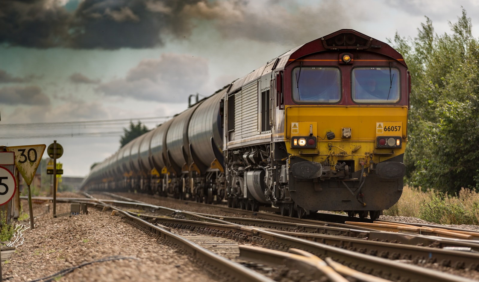
Possessions and safety rules shape every scan and modeling window.
Rail is a linear asset with point assets attached to it. That dual nature creates friction in most building-centric BIM tools. A station can be modeled like a building. A tunnel portal can be treated as a civil structure. But the continuous track alignment—kilometers of geometry with cant, gauge, clearances, catenary, drainage, and signaling—does not behave like a multi-story office.
Typical problems appear early:
Alignment drift. Design alignment and survey control are not locked to one shared CRS and chainage system.
Station/track disconnect. Architectural and structural models of stations are not constrained to the permanent way geometry.
Insufficient existing-conditions data. Brownfield rail work depends on Scan to BIM, but scans are incomplete near live tracks, overhead lines, and platforms.
Interface blindness. Signaling, traction power, telecom, and drainage clash with civil and architectural envelopes only after construction starts.
Possession-driven schedules. Modeling delays that would be tolerable on a building project become schedule killers when work windows are measured in hours overnight.
Owners also struggle with information quality at handover. A federated model that looks visually complete may lack asset IDs, maintainable systems grouping, or attributes required by the railway’s asset management system. Visual BIM without asset semantics is only a 3D drawing set.
For renovation and expansion work—platform lengthening, accessibility upgrades, depot modernization, grade-crossing improvements—the cost of poor existing-conditions models is immediate. Steel packages, precast platform edges, and cable routing all depend on measured reality, not as-designed archives from decades ago.
Why It Happens
Rail BIM failures are usually process failures disguised as software limitations.
1. Wrong tool assumptions. Teams import building templates into linear projects. Levels, grids, and room-based naming do not map cleanly to chainage, track IDs, and corridor zones. Modelers invent workarounds that break interoperability later.
2. Fragmented survey control. Multiple surveyors deliver point clouds and topographic models in slightly different realizations of the same CRS, or mix local project grids with national grids. Millimeter registration inside a station hall can coexist with meter-level drift along the corridor.
3. Incomplete scan planning. Live rail environments limit setup positions. Scanner stations avoid tracks for safety, creating shadows under platforms, behind catenary masts, and inside cable ducts. Modelers then “assume” geometry that later fails fabrication.
4. Weak BIM Execution Plan (BEP) for interfaces. A BEP that lists software versions but does not define alignment ownership, clash matrices for OLE/signaling, or LOD by asset class will not control delivery.
5. LOD confusion. Modeling every rail fastener at LOD 400 across 20 km is wasteful. Modeling only massing for a station where platform edge tolerances matter is negligent. Without an LOD/LOI matrix tied to use cases—clearance checks, prefabrication, FM handover—teams over-model or under-model.
6. Organizational silos. Track engineers, station architects, systems contractors, and operators often work under separate contracts. Federated modeling arrives late, after each package has already optimized locally.
7. Data standards mismatch. EU projects increasingly expect IFC and ISO 19650 information containers. Many US teams still rely on native Civil 3D / Revit / OpenRail packages with PDF and DWG as contractual truth. Without a deliberate exchange strategy, “BIM” becomes a parallel activity that does not govern construction.
Industry Examples (EU/USA)
European Union
European rail programs have pushed BIM harder than most building sectors because corridors cross regions, authorities, and long asset life cycles.
In the United Kingdom and Northern Europe, major station upgrades and high-speed corridor works commonly require ISO 19650-aligned Common Data Environments, federated models for multidisciplinary coordination, and structured asset information at handover. Station projects in dense urban centers use laser scanning extensively: existing platform geometry, heritage façades, and constrained subterranean services cannot be trusted from legacy drawings.
Continental high-speed and metro extensions use corridor models that combine alignment design, earthworks, structures, and systems. Clearance envelopes for rolling stock and pantograph interaction are checked digitally before night possessions. Tunnel and cut-and-cover sections rely on Scan to BIM during construction to verify as-built lining against design tolerances.
A recurring EU lesson is governance: when the appointing party defines information requirements clearly—exchange information requirements (EIR), asset information requirements (AIR), and Level of Information Need—contractors produce usable models. When requirements are vague, teams deliver impressive visualizations that fail FM integration.
United States
US rail BIM practice varies by agency and project type. Transit agencies in large metro areas increasingly require coordinated models for station modernization, ADA upgrades, and yard improvements. Freight and Class I corridors still mix traditional civil design with selective 3D for bridges, tunnels, and complex interlockings.
Examples of practical US adoption include:
Transit station renovations where Scan to BIM captures platform edges, vertical circulation, and MEP congestion before design freeze.
Tunnel rehabilitation programs using laser scanning for deformation monitoring and as-built lining models.
Intermodal facilities coordinating track, roadway, and building packages in one federated environment.
US challenges often relate to contracting. Design-bid-build packages can leave BIM requirements under-specified. Design-build and progressive delivery models perform better when model ownership, update cadence, and clash resolution authority are written into the contract.
Both regions share one truth: rail BIM succeeds when survey, alignment, and systems interfaces are treated as first-class deliverables—not afterthoughts attached to architectural massing.
Technical Explanation
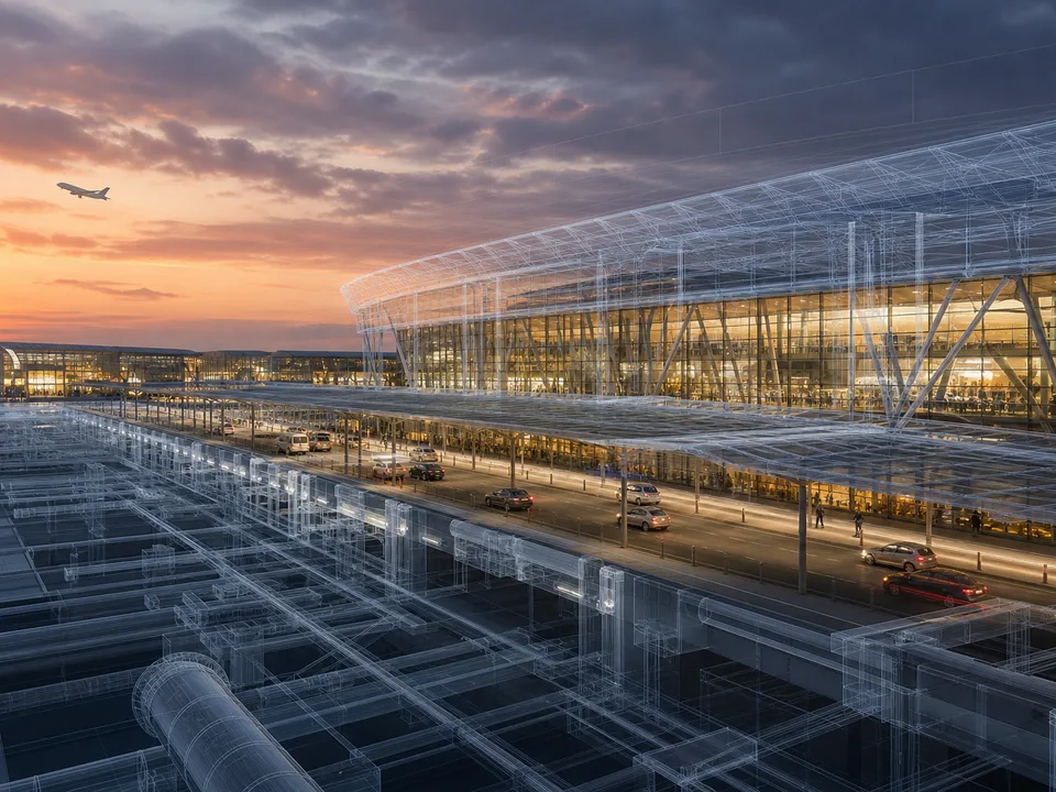
Track, OLE, and station interfaces need strict CRS discipline.
Core model domains
A practical rail BIM federation usually includes:
Alignment and permanent way. Horizontal/vertical alignment, track centerlines, cant, turnouts, and chainage.
Civil and earthworks. Cut/fill, retaining walls, drainage corridors, embankments.
Structures. Bridges, viaducts, tunnels, culverts, station structures.
Architecture. Stations, depots, control buildings, passenger amenities.
MEP and building systems. HVAC, fire, lighting, vertical transportation inside stations.
Existing conditions. Survey control network, point clouds, Scan to BIM as-builts.
Coordinate systems and chainage
Everything depends on a single project CRS and a documented chainage baseline. Station models should be located by control points tied to that baseline, not by approximate site placement. If Revit is used for stations and Civil 3D / OpenRail / Bentley products for corridor work, shared published coordinates and a verified shared reference file are mandatory.
Scan to BIM for rail
Laser scanning supports:
Platform edge and canopy geometry for accessibility and clearance.
Tunnel profiles and deformation baselines.
Station MEP congestion for renovation.
Trackside equipment locations where safe to capture.
Heritage station fabric documentation.
Processing must preserve georeferencing. Decimating clouds for modeling is fine; destroying absolute position is not. Classification helps separate structure, track, vegetation, and temporary construction objects so modelers do not digitize noise.
Clearance and clash logic
Rail clash detection is not only hard clash of solids. Soft clashes and envelope checks matter more:
Structure gauge / kinematic envelope vs platforms, signals, OLE.
Maintenance access envelopes.
Cable tray and duct bank conflicts with civil works.
Temporary works during possessions interacting with permanent design.
Define clash tolerances by system. A 5 mm clash between architectural finishes may be irrelevant; a 20 mm intrusion into a kinematic envelope is not.
Information requirements
Geometry alone is insufficient. Asset classes need identifiers that map to the owner’s asset register: track section IDs, signal IDs, equipment tags, space codes for stations. Agree LOI early—what attributes are required at design freeze vs as-built handover.
Alignment ownership and version control in practice
On multi-contract rail corridors, alignment ownership must be written as a workflow, not a slogan. A practical pattern is to appoint a single alignment custodian—often the civil/track designer—who publishes a versioned alignment package at agreed intervals. Station architects, systems designers, and Scan to BIM teams subscribe to that package rather than maintaining private centerlines. Each published alignment carries a version ID, source software, approval status, and a short changelog. Models that still reference an obsolete alignment are flagged in federation reviews the same way out-of-date architectural links are flagged on building projects.
Chainage discontinuities deserve special attention. Station projects sometimes restart chainage locally for convenience, then forget to map back to corridor chainage used by OLE and signaling. Create a conversion table early and store it in the CDE beside the alignment. When clash issues are written, require chainage references in addition to XYZ coordinates so field teams can find locations during possessions without translating CAD bookmarks under time pressure.
Modeling turnouts, platforms, and OLE interfaces
Turnouts and crossings are interface magnets. Even when full fabrication-level geometry is out of scope, model enough to protect clearances, cable routes, and maintenance access. Platform edges should be treated as tolerance-critical features: Scan to BIM residuals at nosings, coping units, and tactile surfaces matter more than interior finish detail in waiting rooms. Overhead line equipment interfaces with structure, platforms, and kinematic envelopes; incomplete OLE placeholders create false green clash dashboards. If OLE is delivered by a separate contractor, define envelope solids and exclusion zones that other packages must respect until detailed OLE arrives.
Drainage and cable routes along corridors are frequently under-modeled because they are not architecture. They still collide with foundations, noise barriers, and temporary works. A lightweight but continuous representation—aligned to chainage—prevents late surprises more effectively than sporadic detailed islands of modeling.
Information handover for operators
Operators inherit decades of asset life. Handover BIM should map to their asset breakdown structure: track segments, point machines, signals, transformers, rooms, and maintainable equipment. If the operator's CMMS cannot ingest your parameter schema, the model will be shelved. Hold a mapping workshop before as-built production, not after. Include space naming for stations that matches wayfinding and maintenance zones. Provide a known-issues list for areas where scan coverage was limited during possessions—honest gaps are more valuable than invented geometry.
Best Practices
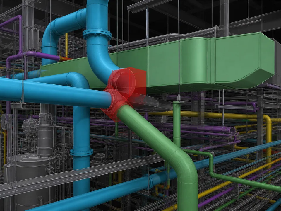
Clash rules must respect dynamic envelopes, not only static solids.
Write a rail-specific BEP. Include CRS, chainage ownership, model federation schedule, LOD/LOI matrix by asset class, and systems clash rules.
Lock survey control before modeling. Do not start Scan to BIM production on floating clouds.
Model for the use case. Clearance models, fabrication models, and FM models are not the same deliverable.
Separate corridor and station authorship clearly. Define interfaces at platform edges, tunnels portals, and building line boundaries.
Use progressive federation. Weekly or biweekly model exchanges beat end-of-phase dumps.
Protect live-railway constraints in the plan. Scan windows, modeling priorities, and construction sequencing must reflect possessions.
Validate with section and envelope checks, not only 3D visuals. Chainage-based sections reveal errors that isometric views hide.
Require QA against point cloud residuals. Spot-check modeled edges vs scan at critical interfaces.
Plan for IFC and native dual delivery when contracts demand it. Map property sets before export week.
Involve operators early. Maintainability and access clearances are often missed by pure design teams.
Step-by-Step Workflow
Step 1: Define information purpose
List use cases: design coordination, clearance assurance, prefabrication, construction sequencing, as-built handover, FM. Each use case drives LOD/LOI and software choices.
Step 2: Establish control and CRS
Publish the project CRS, geoid/height system, control monument list, and chainage definition. Verify that all surveyors and designers sign onto the same document.
Step 3: Capture existing conditions
Plan scans around possessions and track access permits. Prioritize platforms, tunnels, bridges, and congested MEP zones. Capture control targets tied to the monument network.
Step 4: Register, classify, and optimize clouds
Register to control, clean noise, classify major classes, and produce modeling subsets (RCS/RCP, E57, or vendor formats) without breaking georeference.
Step 5: Build the alignment model
Create or import the official alignment. Publish it as the master reference for station placement and systems design.
Step 6: Model structures and stations
Develop station architecture/structure constrained to alignment and survey. Model civil structures with construction joints and interface plates clearly.
Step 7: Model systems packages
Add OLE, signaling, MEP, and cable routes according to the LOD matrix. Avoid decorative detail that does not support coordination.
Step 8: Federate and clash
Assemble models in Navisworks, Solibri, or equivalent. Run hard clash, clearance envelope, and rule-based checks. Assign issues with responsible package and due date.
Step 9: Resolve and freeze
Close critical issues before design freeze and before fabrication release. Document accepted deviations with owner approval.
Step 10: Deliver as-built and asset data
Update models from construction scans where required. Export agreed native + IFC packages with validated attributes and naming.
Case Study
Project type: Urban rail station modernization with platform extension and accessibility upgrades (brownfield corridor).
Context: Legacy drawings from the 1970s conflicted with visible site conditions. Night possessions limited scanning to short windows. The design team needed reliable platform edge geometry, vertical circulation clearances, and congested ceiling voids for new HVAC and fire systems.
Approach:
Established a project CRS tied to the railway control network and verified three primary monuments.
Captured static laser scans of platforms, concourse, and plant rooms across three possession nights; mobile scanning supplemented public areas during limited daytime access.
Registered clouds to control and produced a classified modeling dataset.
Delivered Scan to BIM for architectural/structural existing conditions at an agreed Level of Information Need focused on interfaces, not ornamental detail.
Constrained new platform extension geometry to the permanent way alignment model.
Federated architecture, structure, MEP, and OLE clearance envelopes weekly.
Used clash and envelope reports to redesign duct routes before steel and prefabricated platform elements were released.
Outcomes:
Platform edge tolerances held within the agreed survey residual thresholds at QA checkpoints.
Major ceiling clashes were resolved digitally before possession-based installation nights.
Handover included an as-built federated model with asset tags mapped to the owner’s space and equipment registers.
Rework associated with “unknown existing conditions” dropped relative to the client’s previous station package delivered without Scan to BIM.
The lesson was not software brand. It was discipline: control first, purpose-driven LOD, and continuous federation under possession constraints.
Common Mistakes
Modeling stations in a local origin and “moving them later.” Later never comes cleanly.
Treating point clouds as background pretty pictures. If residuals are not checked, the model is fiction.
Over-modeling track hardware across long corridors. Cost explodes; coordination value does not.
Ignoring kinematic envelopes. Hard clash between solids is not enough for rail.
Late systems involvement. Signaling and OLE interfaces arrive after architecture is frozen.
Undefined chainage ownership. Two packages using slightly different chainage create permanent confusion.
Assuming IFC export will “just work.” Property mapping must be tested early.
No possession-aware scan plan. Critical voids remain unscanned and get guessed.
Handover without AIR compliance. Models fail operator onboarding.
Using building LOD language blindly. Translate LOD/LOI into rail asset terms.
Expert Tips
Create a corridor interface matrix listing every package that touches track, platform edge, tunnel portal, and cable routes.
Maintain a living alignment register—version, source, approval date—so nobody models against an obsolete alignment.
For Scan to BIM, write acceptance criteria as measurable residuals at named features (platform nosing, column faces, tunnel crown), not “model looks good.”
Use section templates at fixed chainages for recurring QA.
Keep temporary works in a separate model discipline so permanent as-builts stay clean.
Train station modelers on rail clearance concepts; do not assume building BIM experience transfers automatically.
When budgets are tight, spend on survey control and critical interface modeling before photorealistic station interiors.
Archive raw scans and registration reports; disputes about existing conditions are common years later.
Future Trends
Rail BIM is moving toward continuous digital twins of corridors: frequent mobile mapping, automated change detection, and asset-linked models updated after every major intervention. AI-assisted classification of point clouds will speed Scan to BIM for tunnels and stations, but human QA on clearances and safety-critical interfaces will remain mandatory.
IFC and openBIM requirements will keep expanding in EU public work. US agencies will continue hybrid native + open exchanges. Expect tighter integration between alignment design tools and building/station platforms, plus more contractual requirements for structured asset data at substantial completion.
Digital permitting and automated code/clearance rule checking will grow, especially for accessibility and fire in stations. The winners will be teams that treat information management as engineering—not as a documentation chore at the end.
Possession planning and BIM production coupling
Rail BIM schedules that ignore possessions become fiction. Scan priorities, model milestones, and fabrication releases must map to available access windows. Produce a simple coupled calendar: capture nights, modeling packages due, coordination workshops, and install possessions. If a capture night fails weather or operational cancellation, the modeling critical path must flex with an explicit change note. Building-project habits of “we will catch up next week” do not translate when the next access is a month away.
Cross-border and multi-authority corridors
Corridors crossing regions may face different CAD/BIM mandates, language requirements, and asset data schemas. Establish a corridor information protocol that sits above local variations: CRS, chainage, naming, and mandatory interfaces. Local packages can extend—but not contradict—the protocol. This is especially relevant for EU cross-border work and for US projects spanning multiple agencies.
FAQ
Is BIM mandatory for rail projects?
Not universally, but many EU public programs and major transit agencies require coordinated models and structured information. Even where not mandatory, complex brownfield stations and tunnels practically need it.
Can Revit alone deliver rail BIM?
Revit is strong for stations and buildings. Corridor alignment and long linear assets usually need civil/rail platforms plus federation. Use each tool for what it does well.
How accurate does Scan to BIM need to be for platforms?
Accuracy must match the use case. Accessibility upgrades and prefabricated edges often need tight survey residuals at the platform nosing and structure interfaces. Define numeric criteria in the BEP.
What LOD should we use for tracks?
Model what coordination and fabrication require. Alignment and clearance-critical elements may need higher detail locally; long tangent track may need less geometric detail but strong attribution.
How do we handle live railway scanning safety?
Through formal access planning, possessions, competent railway protection staff, and scan strategies that minimize track fouling. Never improvise access for “just one more setup.”
Should we deliver IFC?
If the EIR/AIR requires it, yes—and test exports early. Even when not required, IFC can support long-term interoperability for owners.
Summary
BIM for rail projects succeeds when teams respect the linear nature of the asset, lock survey and alignment control early, and model to explicit use cases. Stations, tracks, tunnels, and systems must federate continuously under possession-aware schedules. EU and USA practices differ in standards emphasis, but both reward clear information requirements, measurable QA, and interface discipline. Scan to BIM is often the difference between a coordinated renovation and a possession night lost to field surprises.
CTA
Planning a station upgrade, corridor expansion, or rail Scan to BIM package? Bimzstudio helps engineering and construction teams convert complex existing conditions into coordinated, delivery-ready BIM—aligned to project CRS, LOD/LOI requirements, and real construction constraints. Share your corridor scope and information requirements to discuss a practical modeling approach.