Scan to BIM
Complete Guide to Scan to BIM
Learn Scan to BIM end to end—scanning, registration, modeling, LOD, and QA/QC—for renovation and as-built projects across Europe and the USA.
BimzstudioJan 15, 202514 min
scan-to-bimpoint-cloud
Scan to BIM
Learn Scan to BIM end to end—scanning, registration, modeling, LOD, and QA/QC—for renovation and as-built projects across Europe and the USA.

Scan to BIM is no longer a niche survey add-on. For renovation, fit-out, and facility upgrade work across Europe and the United States, it has become the most reliable way to turn physical buildings into usable digital models. When the process is planned well, you get geometry you can trust for design coordination, prefabrication, and facility management. When it is planned poorly, you get heavy files, misleading accuracy claims, and models that look finished but fail the first clash review.
This guide walks through the full Scan to BIM pipeline the way production teams actually run it: from capture strategy and registration to Revit modeling, LOD decisions, QA/QC, and handover. It is written for BIM managers, survey leads, architects, and owners who need as-built models that survive construction, not just presentation renders.

Most renovation projects start with incomplete drawings. Original construction documents may be missing, outdated, or never updated after decades of tenant work. Field teams often rediscover this late—during demolition, ceiling removal, or MEP rough-in—when a duct riser is 150 mm from where the drawings show it, or a slab edge does not match the architectural plan.
Traditional as-built surveys (tape measures, total stations for a few control points, and hand sketches) cannot capture dense geometry at the speed modern schedules demand. Photogrammetry alone struggles in dark plant rooms and reflective interiors. The industry response has been laser scanning and Scan to BIM: capture millions of points, register them into a coherent cloud, then model the elements that design and construction actually need.
The problem is that “Scan to BIM” is often treated as a single deliverable instead of a controlled process. Teams buy scanner time, dump an RCP into Revit, and expect walls and pipes to appear. Reality is more demanding:
| Challenge | Typical impact |
|---|---|
| Unclear LOD scope | Over-modeling or under-modeling; budget blowouts |
| Weak control network | Global drift, floor-to-floor misalignment |
| Poor registration | Ghost walls, double surfaces, clash false positives |
| No modeling standards | Inconsistent families, unusable schedules |
| Missing QA against cloud | Pretty model that does not fit the building |
Scan to BIM fails when capture, processing, and modeling are disconnected. It succeeds when those stages share one accuracy budget, one coordinate system, and one agreed Level of Development / Level of Detail.
Related reading: Point Cloud to Revit Workflow Explained and BIM for Renovation Projects.
Several structural reasons keep Scan to BIM from being “press scan and model”:
ISO 19650 and national BIM frameworks emphasize information requirements. Scan to BIM is an information delivery method; without Exchange Information Requirements (EIR) and a BIM Execution Plan (BEP), teams invent scope on the fly.
Commercial office retrofit — London / Frankfurt corridor. Landlords converting Category A space need ceiling voids, risers, and façade interfaces modeled for new HVAC. Static terrestrial scans (Leica or Faro class) plus targeted MEP modeling at LOD 300–350 are common. Control is usually tied to a local grid; cadastral georeferencing is secondary unless planning submission requires it.
Healthcare renovation — USA Midwest and Nordic hospitals. Occupied wards limit scan windows. Teams use night shifts, mobile mapping for corridors, and high-resolution static scans in plant rooms. Infection control and restricted access make rescan expensive, so registration and coverage planning matter more than raw scan speed.
Industrial brownfield — ports and process plants in the Netherlands and US Gulf Coast. Pipe racks, vessels, and steel dominate. Scan density and occlusion management become the bottleneck. Clash detection against new process lines drives LOD decisions more than architectural aesthetics.
Historic masonry — Italy, Spain, UK listed buildings. Irregular geometry pushes teams toward hybrid LOD: architectural surfaces at detailed mesh or high-detail walls where interventions land, simplified elsewhere. buildingSMART IFC export is often required for multi-tool teams.
These contexts share one lesson: Scan to BIM scope must follow the decision the model must support—permit, tender, fabrication, or FM—not a generic “full building BIM.”

A production Scan to BIM workflow has five technical layers:
Decide early: project north, shared coordinates, and units (millimeters for most European projects; feet/inches still appear on US imperial jobs). Autodesk ReCap and Revit must agree. A 1:1000 unit mistake is rare but catastrophic; more common is a subtle rotation between survey grid and architectural grid.
More points are not always better. For architectural walls at LOD 200–300, 5–10 mm average spacing on primary surfaces is often enough. For flanged pipe connections and steel connection plates, denser local scans or close-range setups are justified. Blindly scanning everything at highest resolution creates multi-hundred-gigabyte datasets that choke modeling workstations without improving decision quality.
BIM Forum LOD definitions and project-specific LOD matrices remain the practical language of scope:
| LOD | Typical Scan to BIM use |
|---|---|
| LOD 100 | Massing / site context only |
| LOD 200 | Approximate layout for concept and space planning |
| LOD 300 | Accurate geometry for coordination and documentation |
| LOD 350 | Interfaces and connections for detailed coordination |
| LOD 400 | Fabrication-ready detail (selective, expensive) |
| LOD 500 | As-maintained / FM-oriented with verified assets |
LOD should be category-based. A project may need LOD 350 for primary HVAC and LOD 200 for furniture placeholders. See also Revit Modeling from Point Cloud.
Registration quality is often reported as average or RMS cloud-to-cloud residual. Targets give stronger geometric control when visibility is limited. Hybrid registration (targets + cloud-to-cloud) is standard on large buildings. For deeper coverage of failure modes, read Scan Registration Challenges and Why Laser Scanning Fails.
Modelers use section boxes, reference planes, and fitting tools. Walls may be modeled to centerline or face depending on wall type definition. MEP often uses routing preferences and fabrication parts. Structure needs clear rules for member sizes when flanges are partially occluded. Deviation heatmaps (cloud vs. model) close the loop.
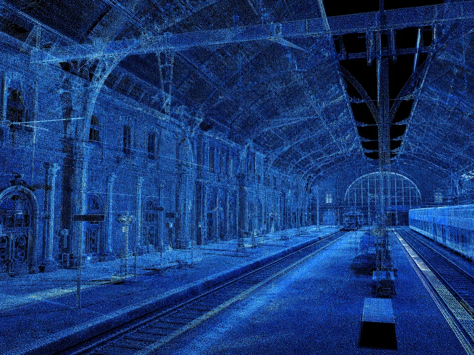
For accuracy-focused planning, see How to Improve Point Cloud Accuracy.
List decisions the model must support: clash detection, demolition drawings, landlord approval, FM asset tagging. Map each decision to categories and LOD. Align with ISO 19650 information containers where the client requires it.
Walk the building with the scan lead and BIM lead. Note reflective surfaces, glass façades, vibration sources, restricted rooms, and areas needing night access. Identify target locations and control points.
Choose instrument class (high-accuracy TLS for plant rooms; mobile for long corridors). Set resolution/quality settings. Define naming conventions for stations. Record temperature and site conditions when accuracy is critical.
Place targets or use feature-rich overlap. Maintain overlapping coverage. Log blackout zones. Capture photos for colorization if needed for client communication (color is rarely required for modeling accuracy).
Import into registration software (ReCap, Cyclone REGISTER, SCENE, Trimble RealWorks, etc.). Resolve residuals. Check floor stacking with vertical sections. Export optimized formats—see Best Point Cloud File Formats.
Link cloud into Revit (or Archicad). Set shared coordinates. Create levels from scanned floor surfaces, not from assumed drawing levels. Agree modeling tolerances (e.g., walls within 15 mm of cloud face for LOD 300 architectural).
Architecture first for hosts, then structure, then MEP—or parallel with clear hosting rules. Use progress tracking by floor and zone. For MEP-heavy scopes, lean on MEP modeling services standards and clash-ready geometry.
Section every X meters. Run cloud-to-model comparison where tools allow. Check openings, slab edges, and pipe centerlines. Document known deviations (warped walls modeled as planar with note).
Export NWC/IFC for clash detection. Produce sheets if drafting is in scope (drafting & documentation). Package cloud index, model, and QA report.
Deliver with a model matrix: what was modeled, what was omitted, and why. Include residual registration stats and deviation summary. That package becomes the project’s as-built truth until the next survey.

Project type: Mid-rise office renovation, Amsterdam metro area
Scope: Architectural + primary HVAC + main electrical trays, LOD 300, ~9,500 m²
Capture: Terrestrial TLS over two weekends + mobile corridor pass
Challenge: Existing CAD plans showed a consistent 3.6 m floor-to-floor; scans revealed local variations of 40–70 mm and a stair core that drifted ~25 mm from the architectural grid.
The Scan to BIM team established control from three exterior benchmarks tied to the local RD grid, registered 186 stations with hybrid targets and cloud-to-cloud (average residual under 3 mm on primary surfaces), and modeled walls to face of finish where finishes were consistent. HVAC mains were modeled to centerline with size verified at accessible flanges.
During design coordination, the mechanical contractor’s new VAV boxes collided with as-built cable trays that drawings never showed. Because trays were in the Scan to BIM model, the clash was found before ceiling demolition. Rework avoided was estimated in the low five figures—more than the incremental cost of including trays in the LOD matrix.
The QA report listed 12 zones where plaster undulation exceeded the planar wall assumption; those zones were flagged for site measure if new partitions landed there. That honesty prevented false confidence and is a hallmark of useful Scan to BIM delivery.
More failure patterns: Common Point Cloud Problems and Solutions.
Scan to BIM is moving toward tighter coupling with digital twins and AI-assisted classification. Autodesk and other platform vendors continue to improve cloud linking and reality capture integrations. SLAM and mobile mapping reduce capture time for large floorplates, while TLS remains the accuracy backbone for plant and structure.
Semantic segmentation (walls, floors, pipes, steel) is improving, but production teams still require human QA for deliverable models. Expect more hybrid workflows: AI proposes elements, engineers verify against cloud and project standards. ISO 19650 information management will keep pushing Scan to BIM outputs into structured CDE workflows rather than email attachments.
On the owner side, Scan to BIM is increasingly the on-ramp to digital twin programs—provided asset data, not only geometry, is planned from day one.
Scan to BIM is the process of capturing a building or site with laser scanning (and sometimes photogrammetry), registering the resulting point clouds, and creating a BIM model that represents as-built conditions at an agreed Level of Development.
Field capture can achieve millimeter-level relative accuracy under good conditions, but the delivered model accuracy depends on registration, control, LOD, and modeling rules. Specify acceptance as a deviation tolerance by category (for example, 10–15 mm for architectural faces at LOD 300), not as a single scanner brochure number.
A small floor may take days; a complex hospital or plant can take weeks to months. Capture is often faster than modeling. Modeling duration scales with LOD, MEP density, and QA requirements.
Usually no. LOD 300–350 covers most coordination. LOD 400 is justified for prefabrication of specific assemblies, not the entire building by default.
Common stacks include Leica Cyclone, Faro SCENE, Trimble RealWorks, Autodesk ReCap, Revit, Navisworks, and CloudCompare for analysis. Choice depends on scanner ecosystem and client deliverables.
No. Structure and MEP are often the highest-value scopes for clash avoidance. Architectural context may still be required as hosts.
For corridors and large open floors, mobile/SLAM can be highly productive. For high-accuracy plant rooms and critical interfaces, terrestrial static scans remain preferred. Hybrid capture is often optimal.
Registered cloud (or structured project), BIM model files, LOD matrix, QA/deviation report, coordinate system statement, and a list of exclusions/occlusions.
Scan to BIM works when treated as a controlled information pipeline: requirements, control, capture, registration, purpose-driven modeling, and cloud-based QA. Europe and USA renovation markets already depend on it for offices, hospitals, industry, and heritage work. The teams that win are not those with the densest clouds, but those with the clearest LOD matrix, strongest registration, and most honest deviation reporting.
Use this guide as a checklist for your next as-built commission, and connect the technical deep-dives on registration, accuracy, formats, and Revit modeling linked above.
If you need production Scan to BIM with clear LOD 100–500 scoping, disciplined QA/QC, and delivery suited to EU and USA project standards, Bimzstudio’s Point Cloud to BIM service focuses on accurate modeling, fast turnaround, and coordination-ready files—including Point Cloud to Revit workflows for renovation and as-built programs.
Continue with the related service, or request a scoped proposal if you already have a brief.
LOD 100 to 500 Explained: How to Specify BIM Detail That Teams Can Deliver
LOD 100 to 500 explained for owners and BIM teams: what each level means, how to specify tolerances, Scan to BIM implications, and QA/QC acceptance criteria.
Point Cloud to Revit Workflow Explained
A production Point Cloud to Revit workflow—from ReCap linking and shared coordinates to modeling, QA, and clash-ready exports for as-built BIM.
Scan Registration Challenges
Solve scan registration challenges—drift, weak overlap, hybrid TLS/mobile seams, and QA—for accurate point clouds and Scan to BIM success.
Owner-confirmed studies that already list this service — visual delivery evidence, not invented metrics.
1105 Lakewood
A Point Cloud → BIM comparison of 1105 Lakewood. The scan and the BIM model share the same viewpoint so the existing condition can be read against the modeled geometry.
18 Grand Avenue
Residential Scan-to-BIM work for 18 Grand Avenue. Cutaway and plan views compare existing-condition scan data with the BIM model. Exterior stills are shown independently and are not used as a slider pair.
Foyer Soleil – Résidence Les Marronniers
Residential BIM for Foyer Soleil – Résidence Les Marronniers. A plan-view scan overlay can be compared with the BIM layout. Exterior elevations are shown as BIM drawings, not as a point-cloud slider.
Telecom Infrastructure As-Built Modeling
As-built BIM for a building with rooftop telecom equipment. The axonometric pair compares an existing-condition capture with the BIM model of the same volume. Façade stills are shown independently.
Language

