Practical methods to improve point cloud accuracy—control networks, scan settings, registration, and QA—for reliable Scan to BIM deliverables.
BimzstudioMay 14, 202512 min
accuracypoint-cloudcontrol surveyregistrationTLSScan to BIMQA/QC
How to Improve Point Cloud Accuracy
Point cloud accuracy is not a single number you buy with a scanner. It is the result of control surveying, instrument setup, environmental management, registration strength, and honest QA. This guide shows how BIM and reality-capture teams improve accuracy on real buildings—so Scan to BIM models in Europe and the USA can support coordination and, where needed, prefabrication.
Control networks and overlap planning beat post-process heroics.
Clients often ask, “Is the scan accurate to 2 mm?” That question mixes instrument specification with project deliverable quality. A better question is: What absolute and relative accuracy do we need, on which surfaces, to support which decisions?
Accuracy problems show up as:
Fabricated pipe that does not bolt up
Curtain-wall brackets misaligned to slab edge
Clash detection that oscillates between false positives and missed hits
Floor-to-floor grid drift that wrecks stair and riser coordination
Disputes between surveyor and BIM vendor about “who is wrong”
Accuracy layer
Typical control method
Instrument ranging
Manufacturer QA, warm-up, proper settings
Setup stability
Tripods, targets, short occupations where needed
Relative registration
Targets + C2C, block checks
Absolute georeferencing
Control survey, known monuments
Modeled deliverable
Modeling rules + deviation reports
Improving accuracy means improving the weakest layer in that stack—not buying a denser scan of a poorly controlled network.
Why It Happens
Spec confusion. Brochure range noise is quoted under ideal albedo and temperature. Real walls are dark, distant, or grazed at shallow incidence angles.
Control is treated as optional. Indoor Scan to BIM jobs skip traversing because “it’s just for Revit.” Floors then disagree.
Registration optimized for speed. Auto-register everything, glance at average RMS, export. Local twists remain.
Wrong capture technology. SLAM for flange-critical racks without periodic absolute updates.
Modeling masquerading as accuracy. Orthogonalizing a leaning wall “improves” drawings and destroys fit.
Industry Examples
Swiss pharma lab upgrade. Required tight coordination for new process pipe. Team established a closed traverse, used high-accuracy TLS, hybrid registration, and deviation heatmaps before modeling LOD 350 MEP. Prefab success tracked back to control and QA—not exotic software.
Texas hospital OR renovation. Night scans only. Accuracy improved by pre-placing targets during daytime access walkthroughs, then scanning quickly at night with known target coordinates. Reduced registration ambiguity under time pressure.
UK rail station concourse. Vibration from operations threatened station stability. Shorter scans, denser setups near critical interfaces, and independent total-station checks on control targets preserved accuracy without shutting the station.
Spanish factory floor. Mobile mapping for layout + TLS pockets for robot cell foundations. Absolute accuracy on cells came from TLS tied to plant survey control; mobile data was constrained to those islands.
Technical Explanation
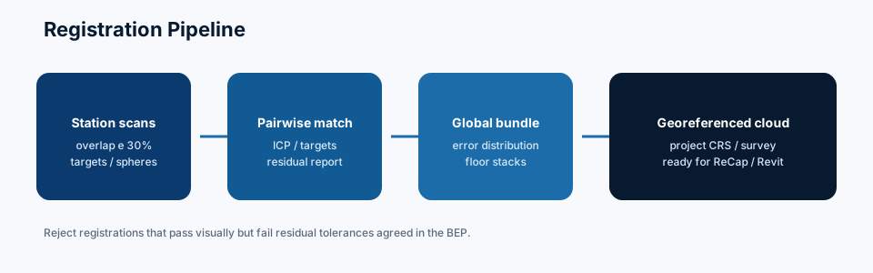
Improve accuracy stage by stage — capture, register, then model.
Relative vs absolute accuracy
Relative: How well parts of the cloud fit each other (critical for clash within one building).
Absolute: How well the cloud sits on a CRS or site grid (critical for civil ties, campus GIS, multi-building sites).
Many renovations need strong relative accuracy and only moderate absolute accuracy. Campus and industrial sites often need both.
Incidence angle and range
Accuracy degrades at long range and shallow grazing angles. Plan stations so primary surfaces are hit more face-on at moderate range. Façade work especially suffers when all setups sit on one sidewalk line.
Target design
Checkerboard and sphere targets remain staples across Leica, Faro, and Trimble workflows. Place them:
Visible from multiple stations
At varying heights (not only floor)
Forming strong geometry (not colinear)
Across block boundaries and floor connections
Cloud-to-cloud statistics
Average residual can hide outliers. Inspect histograms, max errors, and local patches. A 2 mm average with 25 mm local spikes is not a 2 mm cloud.
Temperature and timing
Large steel structures and long exterior campaigns can shift with temperature. For high-stakes industrial work, note conditions and avoid mixing morning/afternoon façade passes without checks.
Linking accuracy to LOD
Decision
Suggested accuracy mindset
Space planning LOD 200
Relative cm-level often OK
Arch coordination LOD 300
~10–15 mm face tolerance common starting point
Prefab MEP LOD 350–400
mm-level relative at interfaces; verify flanges
Campus GIS tie
Absolute per survey spec
BIM Forum LOD speaks to model development; your contract must still state measurable tolerances. RICS measured survey frameworks are useful references when writing those tolerances—adapt to project risk.
Noise vs bias
Noise scatters points around truth; bias shifts the cloud systematically (multipath, refraction, bad scale). Filtering reduces noise; only better setups/control fix bias. See Noise Reduction Techniques.
Best Practices
Validate accuracy against survey control and model-to-cloud deviation.
Write an accuracy budget allocating mm to each error source until the total fits the use case.
Always install or verify control before production scanning on multi-floor or multi-wing sites.
Use hybrid registration (targets + cloud-to-cloud).
Validate with independent checks—total station distances, known column grids, leveled elevations.
Optimize settings for surfaces that matter, not uniformly max everywhere.
Keep primary stations stable—avoid half-collapsed tripods on grating.
QA by block and by floor, not only global reports.
Measure model deviations against the accepted cloud as part of deliverable QA.
Tell the truth about uncertainty in occlusion zones.
Step-by-Step Solution
Step 1 — Define acceptance numerically
Example: “Primary architectural faces ≤15 mm to cloud; steel column centers ≤10 mm relative within a floor; registration block seams ≤5 mm.” Adjust to contract.
Step 2 — Design control
Choose CRS (local engineering grid vs national). Monument density appropriate to building size. Include vertical control for floor stacking.
Step 3 — Plan station network
Overlap, incidence, and inter-floor ties. Mark target coordinates on a plan.
Step 4 — Field capture with checks
After first cluster, register smoke-test. Confirm densities on sample surfaces. Log issues.
Step 5 — Full registration and cleanup
Resolve outliers. Avoid over-smoothing edges needed for fit. Version the result.
Step 6 — Independent validation
Measure 10–20 check distances / elevations not used as registration constraints. Document pass/fail.
Do not “average away” lean beyond policy. Tag deviations.
Step 9 — Cloud-to-model verification
Sections + quantitative comparison tools where available. Peer review.
Step 10 — Continuous improvement
Feed lessons into the next BEP: which rooms needed denser TLS, which corridors were fine with mobile.
Case Study
Project: Cold-storage warehouse conversion, northern Germany Problem: First scan campaign showed good local detail but ~20–30 mm drift end-to-end across a 140 m hall—unacceptable for new racking alignment.
Actions taken:
Established a braced control traverse down the central aisle and along both long walls.
Added elevated targets on rack uprights.
Re-registered in blocks of ~30 m with overlapping control.
Constrained mobile overview passes to the TLS-controlled skeleton.
Validated with total-station check distances every 20 m.
Result: End-to-end relative alignment within agreed 8 mm check tolerance on primary column lines. Architectural Scan to BIM for the envelope proceeded; racking contractor used the validated grid for layout. Extra survey day cost less than one misaligned racking install.
Common Mistakes
Chasing density instead of control
Using only floor targets on tall atriums
Accepting global RMS without local maps
Mixing units when importing control
Validating accuracy only visually in a fly-through
Improving “accuracy” by squaring the Revit model
Decimating before registration QA
Ignoring incidence angle on façades
Letting different floors float on independent origins
No temperature/environment notes on industrial steel jobs
Expert Tips
Build a one-page accuracy budget and attach it to every proposal.
Put at least one vertical target ladder in stairs each floor transition.
Use spheres when incidence varies widely; use checkerboards when facing cameras/scanners squarely.
Color by elevation residual in QA tools to spot bowls and twists.
For SLAM, force loop closures and sprinkle absolute updates.
Keep a calibrated scale bar or known rod on site for quick checks when debates erupt.
Separate cleaning parameters by zone—plant rooms need gentler filters than open offices.
When Autodesk ReCap residuals look fine but Revit disagrees, check shared coordinates before re-scanning.
Photograph control marks so future crews can re-occupy.
Align NBS or client information standards to include accuracy statements—not only file formats.
Building an Accuracy Budget You Can Defend
An accuracy budget allocates millimeters to each error source until the total fits the tightest decision on the project. Example for a prefab HVAC header tie-in targeting roughly 8 mm relative at flanges:
Error source
Allocated (mm)
Control method
Instrument + setup
2
Short range, stable tripod, manufacturer QA
Registration residual
2
Hybrid targets + C2C, block QA
Control / absolute (if needed)
2
Traverse, check distances
Modeling interpretation
2
Multi-section sizing, peer review
Contingency
0–2
Rescan allowance
If the math does not close, either loosen the fabrication tolerance, improve the weak layer, or reduce LOD claims. Marketing a 2 mm scanner while ignoring a 5 mm registration seam is how disputes start.
Relative accuracy recipes for multi-floor buildings
Establish vertical control (leveled benchmarks or well-documented FFLs).
Place targets visible across stair/atrium stations at every floor transition.
Register floors as blocks; join with vertical constraints.
Cut QA sections through every stair and primary shaft.
Validate with independent elevation checks on two columns per floor.
Absolute accuracy recipes for campus and industrial sites
Agree EPSG or local engineering grid in writing.
Occupy or verify monuments before production scanning.
Higher resolution helps define small features; higher quality modes often improve ranging on difficult materials. Neither replaces face-on geometry. Prioritize moderate range to primary surfaces, additional stations instead of max-range heroics, targets at varying heights, notes on temperature for long steel structures, and avoid mixing morning and afternoon facade passes without checks when thermal movement matters.
Validation sampling plans
For a typical mid-rise renovation, a practical validation set might include: 10 horizontal check distances, 6 vertical elevation checks, 4 atrium/stair seam inspections, and 5 local patch residual maps on plant surfaces. Record pass/fail against the BEP table. RICS measured survey thinking is useful when writing these plans—adapt to your risk, do not copy boilerplate blindly.
When to stop improving and start documenting
Past a point, chasing another millimeter costs more than the decision needs. Document remaining uncertainty, especially in occlusions. Accuracy without honesty is still project risk. Pair quantitative checks with clear exclusion lists so fabricators know what was never verified.
Future Trends
Real-time field registration and coverage AI will help crews improve accuracy before leaving site. Multi-sensor fusion (TLS + total station + IMU + photogrammetry) will tighten absolute control. Autodesk and other platforms will continue improving large-coordinate workflows, reducing secondary errors when accurate clouds meet BIM.
Metrology-grade scanning will remain reserved for special industrial cases; most buildings will improve more from better process than from exotic sensors. ISO 19650 information requirements will increasingly include quantitative accuracy acceptance—good news for serious practitioners.
Field Procedures That Protect Millimeters
Accuracy is won or lost before anyone opens registration software. Start each campaign with a warm-up and instrument check per company policy. Confirm the tripod is rigid on grating or soft soils—many “mysterious” residuals begin as setup wobble. Place targets before the first production station, not as an afterthought when auto-registration struggles. Keep a running station log with time, operator, and notes about moving people or operating plant.
On reflective industrial sites, plan incidence deliberately: two stations that see the same flange face-on beat one distant hero scan. On glass-heavy atriums, do not expect C2C alone to save you—targets on slabs and columns are the accuracy intervention. On exterior facades, avoid grazing-only sidewalk lines; add elevated or offset setups where possible.
After registration, run the validation sampling plan before modeling invoices start. If checks fail, fix the network—do not ask modelers to “be careful.” For Scan to BIM production after an accepted cloud, continue with Revit Modeling from Point Cloud and keep deviation reporting as part of deliverable QA, because modeling interpretation remains part of the accuracy chain.
Frequently Asked Questions
What accuracy can I expect from building TLS?
Relative accuracy of a few millimeters is achievable with good control and registration on many indoor jobs. Absolute accuracy depends on the control survey. Always specify both.
Does higher resolution mean higher accuracy?
Not necessarily. Resolution helps define small features; accuracy needs control, geometry strength, and low bias.
How many targets do I need?
Enough for strong geometry across blocks and floors—not a fixed magic number. Sparse targets on a huge floorplate are a red flag.
Can software improve accuracy after the fact?
It can optimize registration and remove noise. It cannot recover missing control or invent unseen surfaces.
Should modelers tighten accuracy?
Modelers should report deviations. Changing geometry to “look accurate” without evidence reduces trust.
Is photogrammetry accurate enough for Scan to BIM?
With dense control and good geometry, photogrammetry can be excellent outdoors. Indoor dark plant rooms usually favor active LiDAR.
How do I specify accuracy in contracts?
State check methods, tolerances by category, residual limits, and acceptance workshops. Reference frameworks from RICS or national survey specs where helpful—do not copy text blindly.
Closing the Loop: From Accurate Cloud to Accurate Decisions
An accurate cloud that never influences design is wasted money. After acceptance, require design teams to reference the cloud version ID on coordination issues. Require fabricators to state which as-built model version they used. When a field fit-up fails, compare against that version before blaming the scanner. Often the failure is a modeling assumption or a post-acceptance design change—not the ranging. Accuracy is a chain; manage every link, including human ones.
Accuracy Improvement Sprint (Two-Week Pattern)
Week 1: Instrument checks, control densification on weak wings, revisit glass/plant station plans, rewrite acceptance tests with independent checks. Week 2: Re-register critical blocks, run C2M on control surfaces, update modeling clouds only after certificate, brief modelers on remaining uncertainty zones.
This sprint pattern repairs programs that already scanned but keep producing “surprising” clashes—usually an accuracy process problem, not a Revit skill problem.
Summary
Improving point cloud accuracy is a systems problem: define tolerances, build control, plan stations for incidence and overlap, register in strong blocks, validate independently, and keep modeling honest. Density alone will not save a weak network. Teams that budget accuracy like they budget schedule produce Scan to BIM that fabricators and coordinators can trust.
Call to Action
Bimzstudio turns qualified clouds into accurate as-built models with disciplined QA/QC, clear LOD 100–500 scoping, and EU/USA delivery standards. For production modeling support, see Point Cloud to BIM and Point Cloud to Revit.